
Product Installation Instructions
ID BPC Logger
| Doc No. | Revision | Date | Platform |
|---|---|---|---|
| ID-BPC-LOGGER | 001 | 11/03/2026 | Universal – ID BPC100 |
Overview
The ID BPC Logger records every CAN channel broadcast by the ID BPC100 brushless pump controller at 100 Hz, saves the data as .csv files to internal memory, and shows live pump data on its display. It is intended for vehicles that have no other way to log BPC data, so it can be mounted anywhere inside the car and does not need to be visible. You will mount the gauge, connect four wires to the BPC IO cable, install the supplied 120 Ω terminating resistor, and confirm the gauge is logging.
What's Included
| Qty | Part No. | Description |
|---|---|---|
| 1 | ID BPC Logger | ID BPC LCD Display and CAN Datalogger. Logs to internal memory, to a .csv file. Integral mounting ears. |
| 1 | — | Pigtail harness, 3 ft — terminated at the gauge, unterminated input end |
| 1 | — | 120 Ω CAN terminating resistor |
| 1 | — | USB-C to USB-A cable (log file download) |
| 2 | — | M6 × 16 mm socket head cap screw |
| 2 | — | M6 flat washer |
| 2 | — | M6 nylock nut |
Tools Required
- 5 mm hex key (M6 socket head cap screws)
- 10 mm wrench (M6 nylock nuts)
- Wire strippers
- Tools for your chosen wire connection method (crimper, soldering iron, heat shrink, etc.)
- PC with a USB-A port, or a USB-C to USB-A adapter
Specifications
| Specification | Value |
|---|---|
| Supply | Switched 12 V — no relay or fuse required |
| Current draw | 0.1 A |
| Operating voltage range | TBD |
| CAN connection | BPC100 CAN Hi / CAN Lo, 1 Mbps (fixed by the BPC100) |
| CAN termination | One 120 Ω resistor across CAN Hi and CAN Lo at the pigtail connection |
| Logging rate | 100 Hz |
| Log file format | .csv — logging starts when BPC CAN traffic is present; a new file starts each time CAN disconnects |
| Internal storage | 500 MB — when full, the oldest files are deleted automatically and logging continues |
| Log download | USB-C port on back of gauge; USB-C (gauge) to USB-A (PC) cable only |
| Display units | Flow: L/h · Temperature: °C |
| Logged channels | Supply Voltage, Supply Current, Motor Current, Flow Rate, Internal Temperature, Duty Cycle, State, Input Duty Cycle, MAP Voltage, Phase, Motor Current Average, Flow Rate Average, Run Time, Diagnostic |
| Mounting fasteners | M6 × 16 mm socket head cap screw, washer and nylock nut behind the panel — hand tight |
| Dimensions | TBD |
| Weight | TBD |
| Operating temperature | TBD |
Installation Steps
1 Choose a mounting location
Mount the gauge inside the car, away from heat and water. It does not need to be visible — its main job is logging.
Leave access to the USB-C port on the back of the gauge so the log files can be downloaded later, and make sure the 3 ft pigtail will reach the BPC IO cable.
2 Mount the gauge
When mounting with the mounting ears, the gauge must be mounted to a flat surface.
Pass an M6 × 16 mm socket head cap screw through each mounting ear and the panel.
Behind the panel, fit a flat washer and then a nylock nut on each screw. Tighten by hand until the gauge is secure.
CAUTION:
The housing is 3D-printed plastic. Hand tight is sufficient — overtightening will crack the mounting ears.
3 Route the pigtail
Route the pigtail from the gauge to the BPC IO cable, clear of heat sources, sharp edges and moving parts. Secure it along the way.
4 Connect power and ground
Connect the gauge red wire to a switched 12 V source. The gauge draws 0.1 A, so no relay or fuse is required.
Connect the gauge black wire to ground.
Use any reliable connection method (solder and heat shrink, crimp splice, etc.) and insulate every joint.
5 Connect CAN Hi and CAN Lo
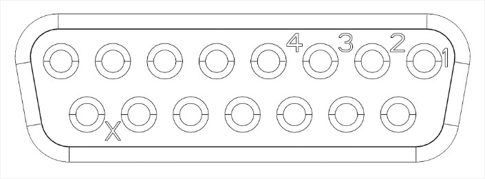
Connect the gauge white wire (CAN Hi) to the BPC IO cable yellow wire (CAN Hi, pin 5).
Connect the gauge green wire (CAN Lo) to the BPC IO cable blue wire (CAN Lo, pin 6). Insulate both joints.
| Signal | Wire Color | IO Cable Pin | Description |
|---|---|---|---|
| ON/OFF | Red | 1 | Ignition switched, battery +, hot during cranking, 7 vdc (min) |
| ON/OFF Ground | Black | 9 | Ground for turning on controller |
| PWM + | Red / White | 2 | PWM positive input, 5 vdc (min) |
| PWM – | Black / White | 10 | PWM negative input, ground |
| Flowrate Power | White | 3 | Power supply (input) for Flowrate circuit, 5 vdc (min) |
| Flowrate Ground | Brown | 11 | Ground for Flowrate circuit, chassis ground |
| Flowrate Signal | Pink | 4 | Digital signal output to logger for flowrate datalogging |
| CAN Hi | Yellow | 5 | CAN IO Hi |
| CAN Lo | Blue | 6 | CAN IO Low |
| MAP Ground | Green | 14 | Ground output to MAP sensor |
| MAP Power | Orange | 15 | 5 vdc output to MAP sensor, 20 mA max. ONLY USE FOR MAP SENSOR |
| MAP Signal | Purple | 8 | MAP sensor signal input, 0.5 to 4.5 vdc |
Figure 1: BPC100 IO cable (DB15) pinout, looking into the controller side (X = pin 15). CAN Hi is yellow, pin 5; CAN Lo is blue, pin 6
6 Install the terminating resistor
Connect the supplied 120 Ω resistor across CAN Hi and CAN Lo at the connection point of the pigtail. Insulate the resistor leads so they cannot touch each other or ground.
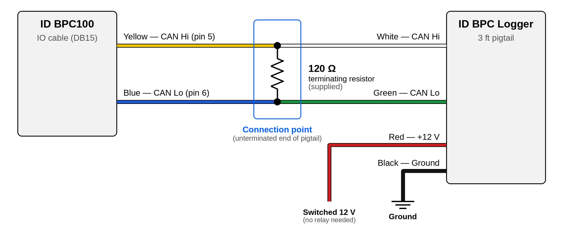
Figure 2: CAN, power and ground wiring — ID BPC100 to ID BPC Logger
CAUTION:
Without the 120 Ω resistor in place, the gauge will not receive reliable data from the BPC.
7 Power up and check the display
Turn the ignition on. The gauge shows the ID logo while it boots, then switches to live data: VOLT, FLOW, AMP, TEMP and DUTY.
Logging starts automatically whenever the BPC is sending CAN data. No button or setup is required.
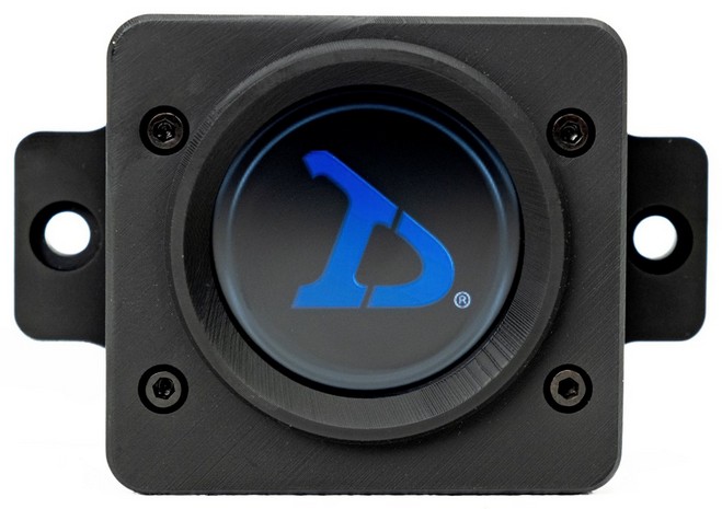
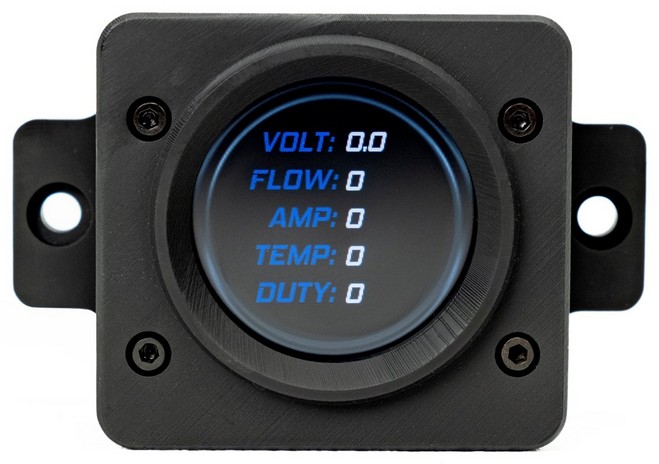
Figure 3: Boot screen (left) and live data screen (right)
8 Download the log files
With the gauge powered (12 V and ground connected), plug the supplied USB-C to USB-A cable into the USB-C port on the back of the gauge and into a USB-A port on the PC.
The gauge switches to DOWNLOAD MODE and appears on the PC as a removable drive. Copy the .csv files to the PC. Logging pauses while the USB cable is connected.
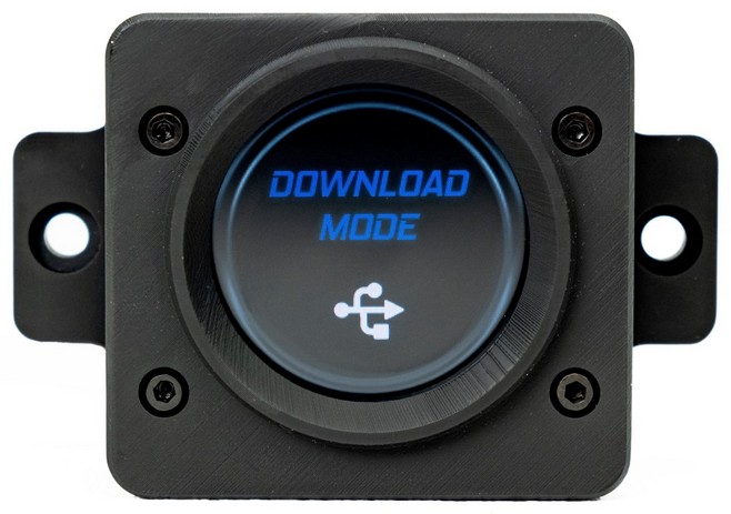
Figure 4: Download mode screen
NOTE:
Use a cable with USB-C at the gauge end and USB-A at the PC end. A direct USB-C to USB-C cable will not work. If the PC has no USB-A port, use a USB-C to USB-A adapter.
9 Manage stored files
The gauge holds 500 MB of logs. When memory is full, it deletes the oldest files automatically and keeps logging. To clear space sooner, delete files from the gauge while it is connected to the PC.
Post-Installation Check
- Gauge is mounted securely and all wiring is insulated, secured and clear of heat
- Gauge boots to the ID logo, then shows live data with the BPC powered
- VOLT reads close to battery voltage; FLOW and DUTY respond when the pump runs
- A test log downloads to a PC and opens correctly
Support
Questions about this installation? Contact Injector Dynamics at 214-607-9022 or support@injectordynamics.com, or visit injectordynamics.com.
Injector Dynamics · injectordynamics.com · ID-BPC-LOGGER Rev 001